En comparant deux Affichage LED COB P1.2 quotations, the real question is whether the additional cost of COB delivers the protection, image quality, or maintenance benefits your project needs.
The answer depends on the installation. A higher COB price may be justified if its advantages are visible at the intended viewing distance, lighting, and operating brightness, with dependable spare parts and repair support. If SMD already meets the display requirements, contact risks are controlled, and local service is established, it may offer better value.
Start by understanding the packaging differences, then establish a fair comparison. Actual content, itemized costs, and a clear recovery process should determine whether the premium is worthwhile.
1. What Are SMD and COB LED Technologies?
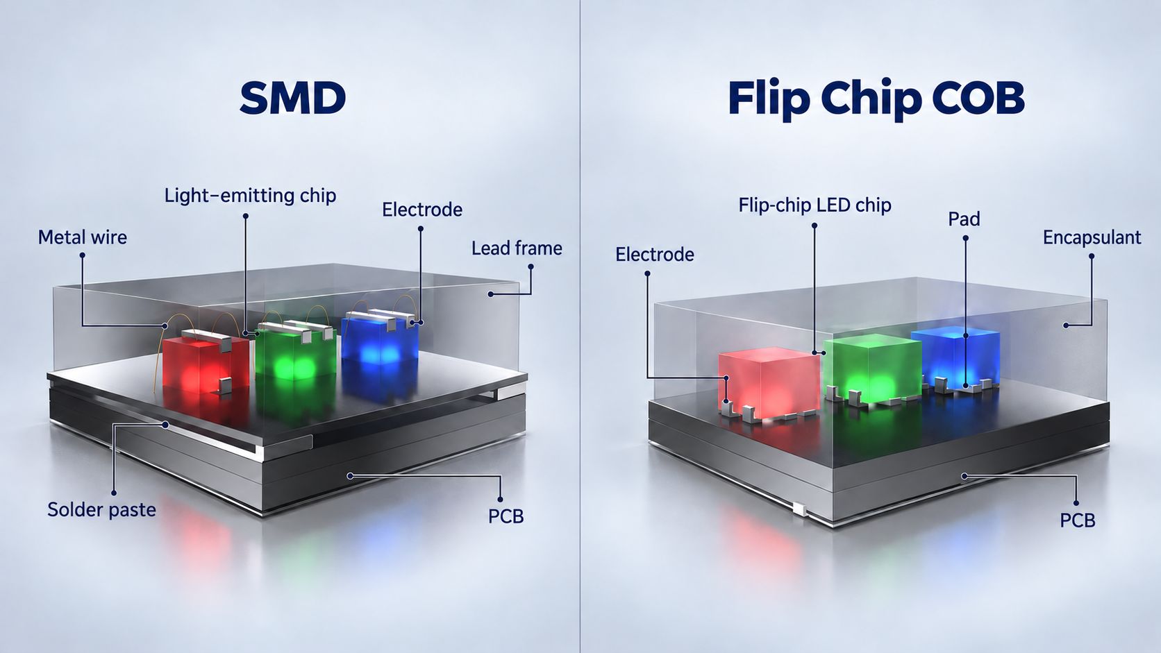
SMD and COB differ mainly in how LED chips are packaged. This affects surface protection, viewing characteristics, and repair options.
SMD (dispositif monté en surface)
LED chips are packaged into individual devices, which are then soldered onto the module circuit board. Common full-color SMD devices contain red, green, and blue chips in one package. Individual devices can be replaced, but component-level repairs at P1.2 require specialized tools and skills.
COB (puce intégrée)
LED chips are mounted and electrically connected directly to the circuit board, then covered with protective encapsulation. A continuous surface can reduce direct chip exposure to contact. Chip-level repairs generally require specialist support.
At the same actual pitch and pixel matrix, both technologies have the same native resolution. Packaging provides different protection and repair characteristics; image quality, power consumption, and reliability remain product-specific.
2. What Are the Pros and Cons of P1.2 COB and SMD?
These construction differences create distinct benefits and limitations. The following points describe common product forms; verify them against the quoted model.
Avantages de l'ÉPI
-
Continuous encapsulation can reduce direct contact with LED chips.
-
The surface may appear more continuous at close viewing distances, with less visible individual-device structure.
-
Suitable surface treatment, driving, and calibration can deliver the required black appearance, low-brightness grayscale, and uniformity.
COB Disadvantages
-
Chip-level repairs generally depend on specialist equipment and processes.
-
A potentially higher purchase price requires evidence of useful project benefits.
-
Encapsulation can still reflect light, vary in gloss, or sustain damage. Cleaning must follow product restrictions.
SMD Advantages
-
Comparable configurations may offer a lower initial purchase cost.
-
Individual devices provide a component-level repair path for qualified teams.
-
Established local support can make use of existing personnel, tools, and compatible spares.
SMD Disadvantages
-
Exposed devices without additional protection require care during handling and cleaning.
-
Device outlines and surface structure may be more noticeable at close range.
-
Dense P1.2 layouts can make component repairs difficult; repairability does not guarantee faster recovery.
Both technologies may support on-site module replacement. If SMD uses GOB or another protective treatment, assess the finished surface and its repair requirements rather than applying assumptions about exposed SMD.
Before comparing these benefits, confirm that the two “P1.2” quotations provide a comparable display configuration.
3. How Do You Verify P1.2 Specifications and Native Resolution?
The “P1.2” product label should not be taken as confirmation of the actual pixel pitch. Buyers should check the Pixel Pitch specification and obtain written confirmation from the supplier, rather than use the model designation to calculate display dimensions or resolution.
For example, the product page for Premteco's Écran LED COB 4K innovant lists the Item as «P1.2» and the Pixel Pitch as 1.26 mm. Buyers therefore need to check the product designation and pixel pitch separately, rather than assume that “P1.2” means an actual pitch of 1.20 mm.
Demandez le module active display dimensions, module pixel matrix, cabinet active display dimensions, and cabinet pixel matrix for the same configuration. Check that these specifications are consistent. Do not mix data from different versions or configurations. If discrepancies appear, obtain a clarified specification sheet and cabinet layout drawing.
Calculate the wall’s native resolution from the cabinet pixel matrix and cabinet arrangement. The following example illustrates the calculation only. Assume each cabinet has a confirmed resolution of 480 × 270 pixels, arranged in a regular grid of eight cabinets across and eight cabinets high:
Wall width in pixels: 480 × 8 = 3840
Wall height in pixels: 270 × 8 = 2160
This arrangement provides a native resolution of 3840 × 2160 pixels. Calculate the active display dimensions separately using the selected cabinet’s active width and height—not the “P1.2” label. The final proposal should specify the cabinet arrangement, total active display dimensions, and complete wall pixel matrix.
Distinguer également 4K input from native 4K. In this article, native 4K (UHD) means a physical display matrix of 3840 × 2160 pixels. A processor’s ability to accept a 4K signal does not mean the LED wall has that resolution. Downscaling 4K content to a lower native resolution may reduce detail in small text and fine lines.
Before purchasing, obtain supplier-confirmed, consistent specifications for the actual pixel pitch, cabinet configuration, active display dimensions, and wall native resolution. For more on the relationship between pixel pitch, display dimensions, and native 4K, see COB LED wall size and resolution.
4. Which Project Conditions Affect COB and SMD Selection?
Once the configurations are comparable, assess whether packaging differences matter during normal use. Viewing, contact, and reflections shape the experience; budget and purchasing preferences determine how those benefits are valued.
4.1 Close-Range Text: Separate Surface Appearance from Readability
COB may make individual-device outlines less noticeable, while exposed SMD structure may be easier to see. This can affect viewing comfort, but does not give COB more text detail.
With the same pixel matrix, readability depends largely on font size in pixels, layout, scaling, and signal processing. Check comfort from the nearest seat and essential text from the farthest required reading position.
Use actual presentations, spreadsheets, and monitoring interfaces with the final split-screen layout. If both displays struggle, review the matrix and layout first. See choosing pixel pitch for viewing distance and content.
4.2 Maintenance Contact: Consider Protection and Repair Together
COB protection may be valuable where presenters, cleaning, installation, or module handling create contact risks. Unprotected SMD requires greater care around exposed devices.
High foot traffic alone does not establish a risk. Identify what can touch the screen, then check permitted handling and cleaning methods.
SMD component repairs require approved tools and skills. COB chip repairs may need specialist support, while module replacement can restore operation first. Treat damage prevention and recovery speed as separate benefits.
4.3 Black Surfaces: Check Reflections and Shadow Detail
COB encapsulation and SMD devices, masks, or surface treatments can all influence black appearance.
Compare the powered-off surface, ambient reflections, and operating shadow detail separately. A darker unpowered surface does not guarantee better near-black reproduction.
Use actual ceiling lights, windows, and side seating. Check whether reflections obscure content or neighboring modules differ in color or gloss. An advantage visible only in a dark showroom may have limited project value.
4.4 Budget: Connect Additional Spending to Useful Benefits
SMD savings may fund spares, processing, mounting, or local service. COB’s premium should address a defined need, such as unavoidable contact or a verified viewing improvement.
Outdoor, high-brightness, and rental installations also need appropriate finished products. Brightness, weather resistance, transport protection, assembly speed, and structural safety cannot be inferred from packaging alone.
4.5 Purchasing Preferences: Turn Labels into Requirements
Buyers may favor COB's surface appearance or prefer familiar SMD maintenance. Convert either preference into requirements: readable text, distinguishable shadows, approved cleaning, and uniformity after replacement.
COB must justify its premium; SMD must demonstrate that lower spending still meets the requirements. Claims such as “newer”, “more reliable”, or “more efficient” need product evidence.
5. How Do You Compare COB and SMD Project Costs?
With the required benefits defined, check how the quotation prices them. Cost per square meter is useful for screening, but a project comparison needs the complete scope.
|
Élément de coût
|
Que confirmer
|
|
Écran
|
Actual pitch, matrix, electronics, surface treatment, redundancy
|
|
Contrôle et traitement
|
Inputs, capacity, scaling, windows, licenses
|
|
Montage
|
Structure, alignment, service space, finishing
|
|
Livraison et installation
|
Packaging, freight, taxes, handling, commissioning, calibration
|
|
Pièces de rechange
|
Modules, power supplies, receiving cards, versions, storage
|
|
Garantie et réparations
|
Labor, freight, response, replacement arrangements, responsibilities
|
After aligning the scope, calculate the COB premium and identify what it purchases. Well-supported SMD may suit a downtime-sensitive project better than COB with inadequate recovery support.
5.1 How Should Power and Heat Be Included?
Measure input power using the same area, brightness, white point, content, and operating conditions. Different “typical power” figures are not a fair comparison.
COB power consumption also depends on chips, drivers, power supplies, and supply architecture. One efficient product does not establish a category-wide advantage.
Lower surface temperature does not necessarily mean lower power consumption. Evaluate electricity costs and room heat load from measured power and operating hours; assess component temperatures under the final installation conditions.
Verified savings can enter the cost comparison.
Without dependable failure data, avoid precise payback claims. Instead, price one failure scenario—diagnosis, replacement, repair, and shipping—and check whether spare stock covers the repair period. Assess business losses from downtime separately.
6. How Do You Test P1.2 COB and SMD Image Quality?
Validate quoted image-quality benefits using samples that match the delivery configuration. Record the model, driving and control configuration, calibration status, and software settings.
6.1 Align the Test Conditions
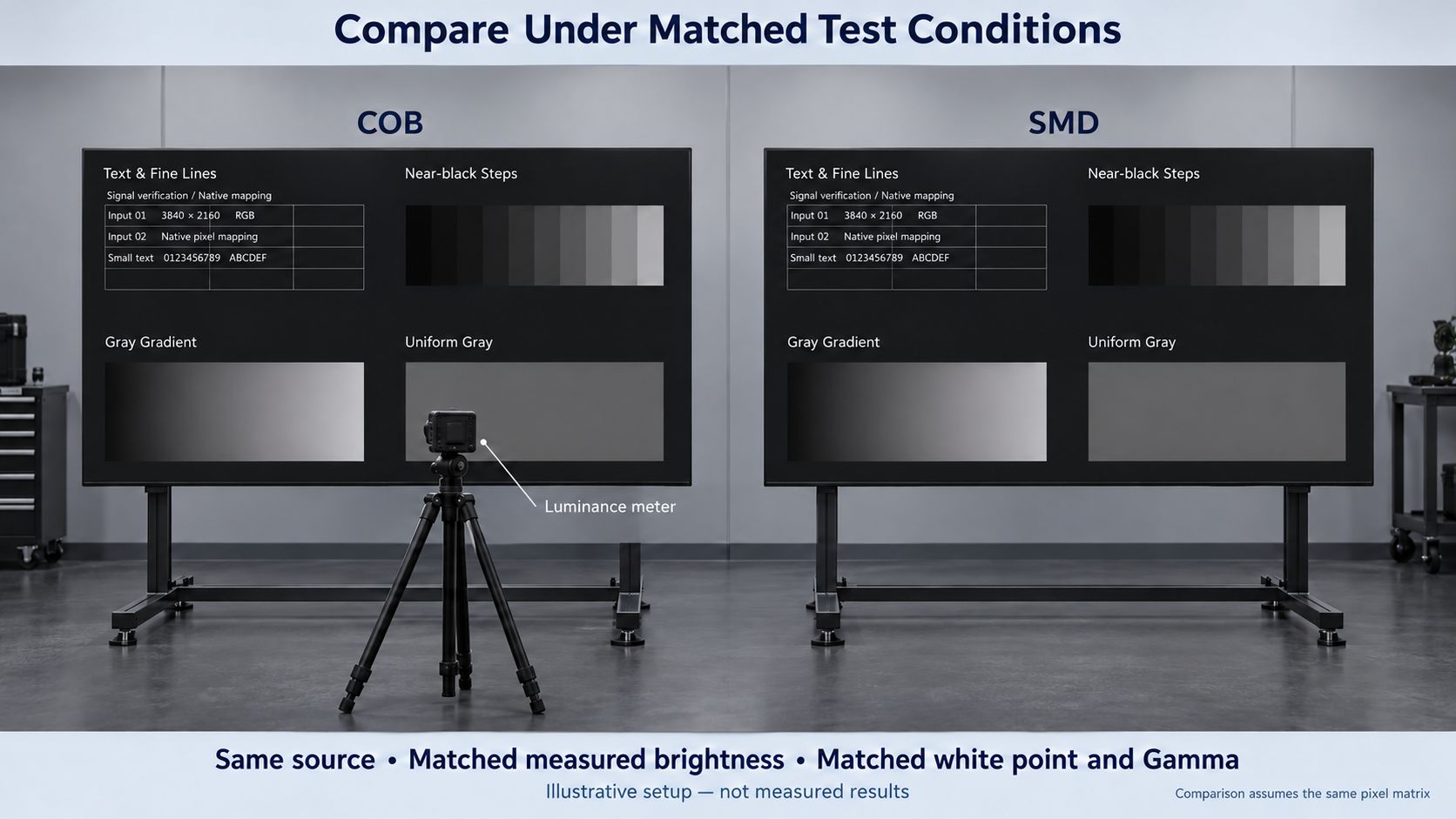
Use identical source files, signals, and scaling, with comparable white point, Gamma, and lighting. Gamma describes the relationship between input grayscale and displayed brightness.
Set both displays to the same measured operating brightness; equal percentage settings do not guarantee equal output.
If matrices differ, inspect each at native resolution, then compare through the planned project signal chain.
6.2 Check Four Essential Content Types
Use content that reveals task performance rather than relying on vivid demonstration videos.
|
Contenu du test
|
Ce qu'il faut observer
|
Purchasing Relevance
|
|
Actual text, tables, fine lines
|
Readable numbers, missing strokes, split-screen text size
|
Matrix, layout, processing suitability
|
|
Near-black steps
|
Distinguishable levels, color shifts
|
Shadow detail at operating brightness
|
|
Gray gradients
|
Banding, abrupt steps, tint changes
|
Driving and grayscale mapping
|
|
Uniform gray across modules
|
Brightness or color patches
|
Wall consistency and calibration
|
Low-gray and full-grayscale calibration require dedicated treatment; maximum-brightness video cannot replace low-brightness testing.
Check actual side seating and repeat observations after normal operating temperature is reached.
6.3 Verify Camera Performance with the Specified Equipment
Broadcast, streaming, and XR projects require camera tests. Refresh behavior, scanning, driver settings, synchronization, lenses, distance, and exposure all matter.
Use the intended cameras, lenses, frame rates, and shutter settings. Check bands, flicker, moiré, color, and shadows across planned camera positions and movement.
COB offers a purchasing benefit only if the quoted product performs better under these conditions. Phone photographs can document issues, but automatic processing makes them insufficient as standalone evidence.
7. How Do You Assess Reliability and Maintainability?
Image tests establish task performance; reliability assessment examines sustained operation and recovery.
Surface protection addresses one risk category. Power supplies, receiving cards, connections, soldering, and thermal design also affect stability. Request model-specific records stating samples, conditions, duration, limits, and results.
Chip brands and dimensions cannot replace finished-product assessment.
Thermal evidence should reflect ventilation, room temperature, content, and brightness in the final installation.
7.1 Confirm Continuous-Operation Support
For control rooms or extended operation, check permitted conditions, power and signal redundancy, monitoring, service access, and spares.
COB is not maintenance-free, and SMD can also support continuous operation. Confirm whether local failures affect the whole wall and whether recovery interrupts business.
7.2 Separate On-Site Recovery from Specialist Repair
Restoring the display and repairing the failed part may follow different processes:
-
On-site recovery: diagnosis, access, compatible spares, settings, calibration.
-
Specialist repair: location, process, charges, return time.
Demonstrate an approved module replacement, including isolation, replacement, configuration recovery, and uniformity checks. Do not assume hot swapping is permitted.
Rental and touring projects also need evidence of repeated assembly, connector durability, transport protection, and independent unit replacement.
8. P1.2 COB vs SMD: A 30-Second Selection Guide
① Choisissez le format CMS si :
-
Questions budgétaires : tested image quality meets requirements at a better total price.
-
Local repair matters: support exists for the specific model.
-
The project is outdoor or high-brightness: the product meets environmental requirements.
-
It is rental or touring: assembly and independent replacement are supported.
-
Contact risk is low: COB offers little practical surface benefit.
② Choisissez COB si :
-
Close viewing matters: tested surface appearance better meets the need.
-
Contact is frequent: protection evidence covers expected handling.
-
Cameras are involved: specified shooting tests show better performance.
-
Downtime limits are strict: verified quality and recovery support are better suited.
-
Operating costs matter: measured savings justify the premium.
9. P1.2 COB and SMD FAQs
Q1: Can Existing SMD Cabinets Accept COB Modules?
A1: Do not assume compatibility. Confirm dimensions, connectors, power, driving, receiving-card support, and calibration, with supplier approval for the exact combination.
Q2: How Many Spare Modules Are Needed?
A2: Base stock on module count, replenishment and repair times, downtime limits, and service commitments. Verify version compatibility, optical matching, storage, and calibration data.
Q3: What Should a Dead-Pixel Warranty Specify?
A3: Define defects, thresholds, remedies, reporting, labor, shipping, and accidental damage responsibilities. Warranty length alone does not establish recovery time.
Q4: Is Delivery Acceptance Still Needed After Sample Testing?
A4: Yes. Include approved configurations, content, and test conditions in the purchase specification, with acceptance requirements for the complete wall and replacement modules.
10. Conclusion
Judge P1.2 COB and SMD by actual resolution, usable image quality, handling risks, and recovery capability. COB‘s premium is justified when its benefits solve a real need. SMD remains valuable when it meets requirements with better cost and support.
Fournir un Premteco with active dimensions, viewing positions, content samples, lighting, and maintenance requirements to compare configurations and define the evidence needed for demonstrations and quotations.




