A COB LED cabinet goes dark shortly before an event. With upstream power and signal faults ruled out, should the crew exchange a complete power and control assembly, or identify the failed PSU, receiving card, or HUB board first?
That decision determines how far the crew must investigate, what they must dismantle, and which spares they need. An Integration design may shorten restoration but tie up a complete assembly for one fault.
A separate design can limit replacement to the failed part, although diagnosis and access may take longer. COB describes LED chip packaging, not cabinet electronics.
Here, integrated means functions share a board or replaceable assembly. Separate means the PSU, receiving card, and HUB board are relatively independent service units. Check the proposed product.
Identify the Four Electronic Functions Before Comparing Designs
“Three in one” may mean boards housed together or functions on one printed circuit board. Confirm both the physical layout and the field replacement procedure.
|
Function
|
What it does
|
What to identify in the cabinet drawing
|
|
Power supply unit (PSU)
|
Powers electronics and LED modules
|
Location, connections, and independent removal
|
|
Receiving card
|
Receives display data for the modules
|
Separate card, shared PCB, or combined assembly
|
|
HUB board
|
Connects receiving card and modules
|
Board boundary, connectors, and removal path
|
|
LED driver ICs and circuits
|
Drive LED pixels
|
Module PCB or separate board; replacement unit
|
Ask the supplier to outline all four functions, PCBs, and connections between boards on the quoted cabinet drawing. Functions on one PCB are on the same board; different boards within one enclosure are merely in the same box.
Mark each field spare number. The manual may permit individual board replacement or require a whole-box exchange despite separate internal boards. The latter is what must be replaced together means.
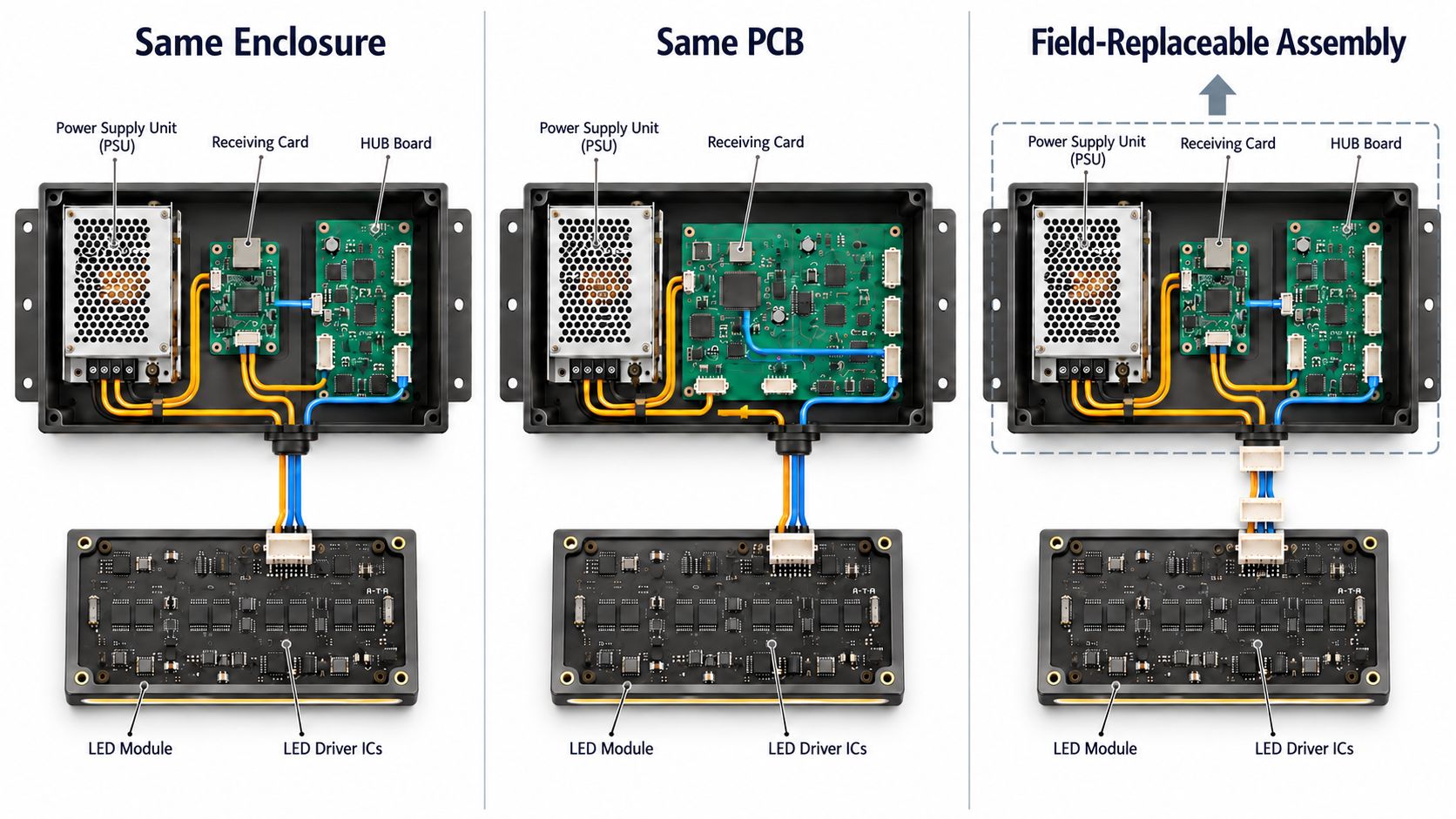
These boundaries match failures to spares. An LED module driver fault may remain after a power and control exchange; a receiving-card fault may require a whole-assembly spare.
Request both a board drawing and a service drawing. The first identifies functions; the second shows screws, connectors, and the order in which a technician removes parts.
Integrated vs Separate Electronics: Benefits and Trade-Offs
An integrated design can move detailed diagnosis from the venue to the repair shop. A separate design can reduce the hardware replaced on site. Each advantage depends on access and available skills.
Integrated Electronics: Reduce Internal Connections and On-site Work
Combining a receiving card and HUB board may eliminate their interconnecting cable. A removable power and control assembly lets technicians exchange it before diagnosing its boards.
Actual reductions in connections and assembly steps depend on the layout. Integration alone proves neither lower cost nor higher reliability.
If only the receiving-card function fails, does the crew use a spare containing a working PSU and HUB? That matters to teams exchanging complete units during events.
Confirm repair responsibility and advance replacements. Event fleets may need circulating stock while removed assemblies await repair.
Price the complete spare and its repair cycle, including freight. Otherwise, a low installation price can conceal the cost of keeping enough assemblies ready for several simultaneous jobs. Include spare utilization, freight, and downtime in the total COB LED display cost when comparing the two designs.
Separate Electronics: Limit Replacement to The Failed Part
With individually replaceable boards, a skilled team uses only the failed part. Compatible spares may serve several projects.
In some COB cabinets, technicians must remove an LED module and HUB board to reach the receiving card behind them. A small spare does not guarantee a quick repair.
Check tools, clearance, adjacent modules, and cabinet alignment.
For rentals, assess connector retention and cable strain after repeated setups. For wall mounting, test the removal path against the frame and service opening. Also check field repair levels, approved cleaning methods, and spare compatibility in the guide to COB LED Display Maintenance, Repair, Cleaning, and Spare Parts.
Use the quoted cabinet, manual, and spare prices to verify this comparison:
|
Service Factor
|
Integrated Design
|
Separate Design
|
|
Internal connections
|
Some layouts reduce cables and connectors
|
Connections between boards and cables need management
|
|
On-site replacement
|
One assembly can be exchanged, even for a single failed function
|
Only the failed part may be replaced, but reaching it may take longer
|
|
Spare stock
|
Fewer spare types may simplify stock; price each complete assembly
|
Parts can be stocked in combinations; track more models and revisions
|
|
Local repair
|
Suits whole-unit exchange followed by centralized repair
|
Suits teams equipped for diagnosis and replacement of individual parts
|
|
Long-term compatibility
|
A future assembly must fit the existing cabinet
|
A future board must match interfaces, power, firmware, and neighboring parts
|
How Does the Architecture Change Recovery Time for the Same Fault?
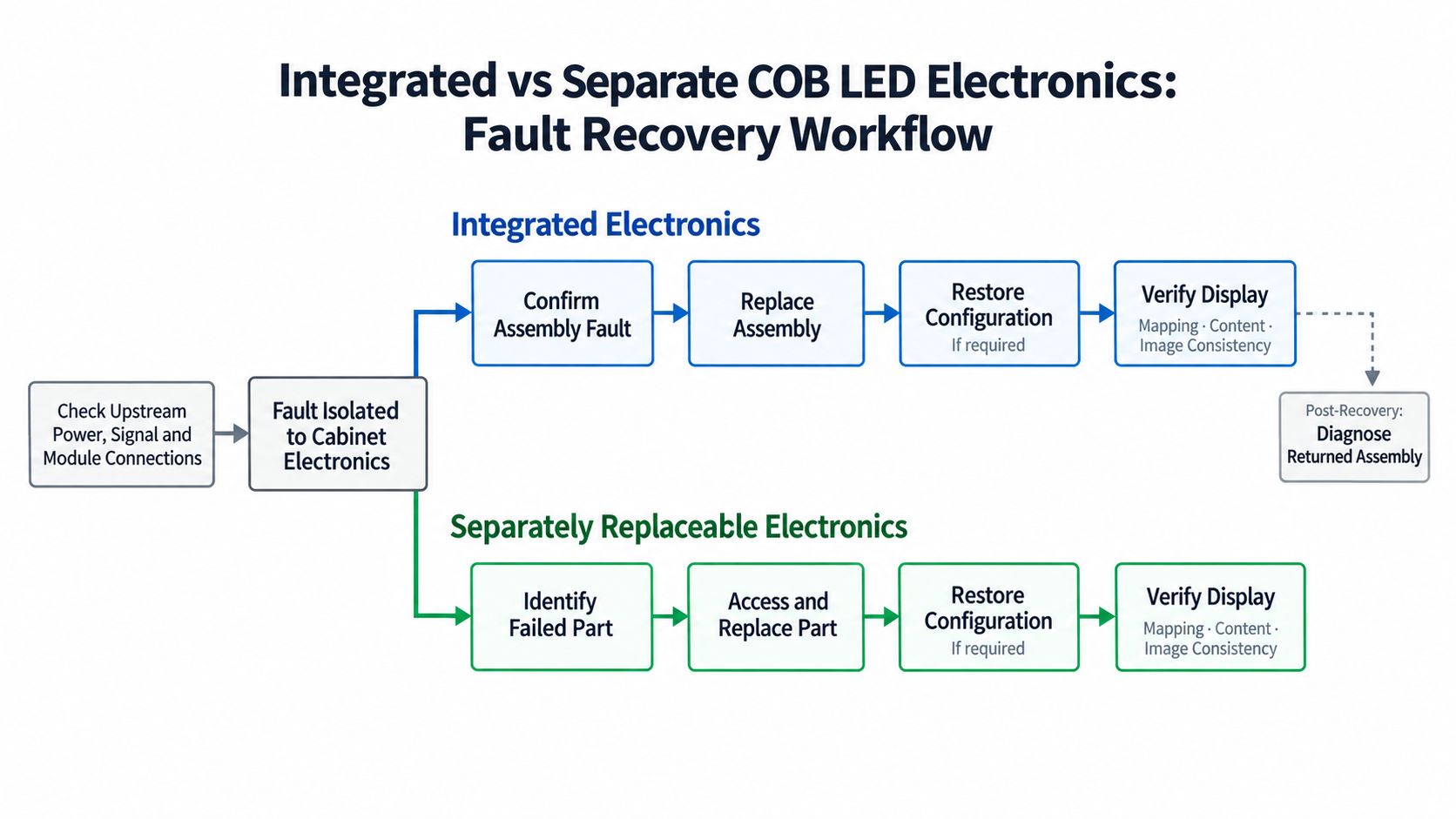
With compatible spares on site, first establish whether one cabinet or several along the signal chain are dark. Check upstream power, input signal, cabinet status, and module connections according to the manual.
After isolating cabinet electronics, the repair paths diverge.
Integrated: Defer Diagnosis of Individual Parts Until After Restoration
If a removable power and control assembly contains the fault, technicians install a compatible spare and identify the failed internal function later.
Diagnosis and removal of individual boards move out of the outage window. That helps crews trained to exchange assemblies under a strict event deadline.
This requires installed access, an on-site spare, and recoverable configuration. It cannot fix faults outside the assembly.
Separate: Identify the Failed Part Before Replacing It
Technicians distinguish PSU, receiving-card, HUB-board, and connection faults. Clear indicators and accessible parts can make this quick while consuming only the needed spare.
Removing one board to reach another can prolong the outage despite a cheaper replacement part.
Stop the Clock After the Image Passes Inspection
Time fault isolation, access, replacement, configuration recovery, and image verification separately. After a receiving-card exchange, check mapping, content, brightness, and color.
Confirm whether the spare is programmed and how configuration and calibration are restored; automatic recovery varies by system.
For a 30-minute restoration target, a five-minute mechanical exchange proves little. The image must pass inspection within the limit. At remote sites, include spare delivery time.
Have the technician who will maintain the wall run the exercise using the supplied tools and files. Record a separate result for a simulated PSU failure and receiving-card failure.
Test on the proposed mounting structure. A bare workbench cabinet does not reveal trim and clearance restrictions.
How to Choose COB Electronics for Your Project
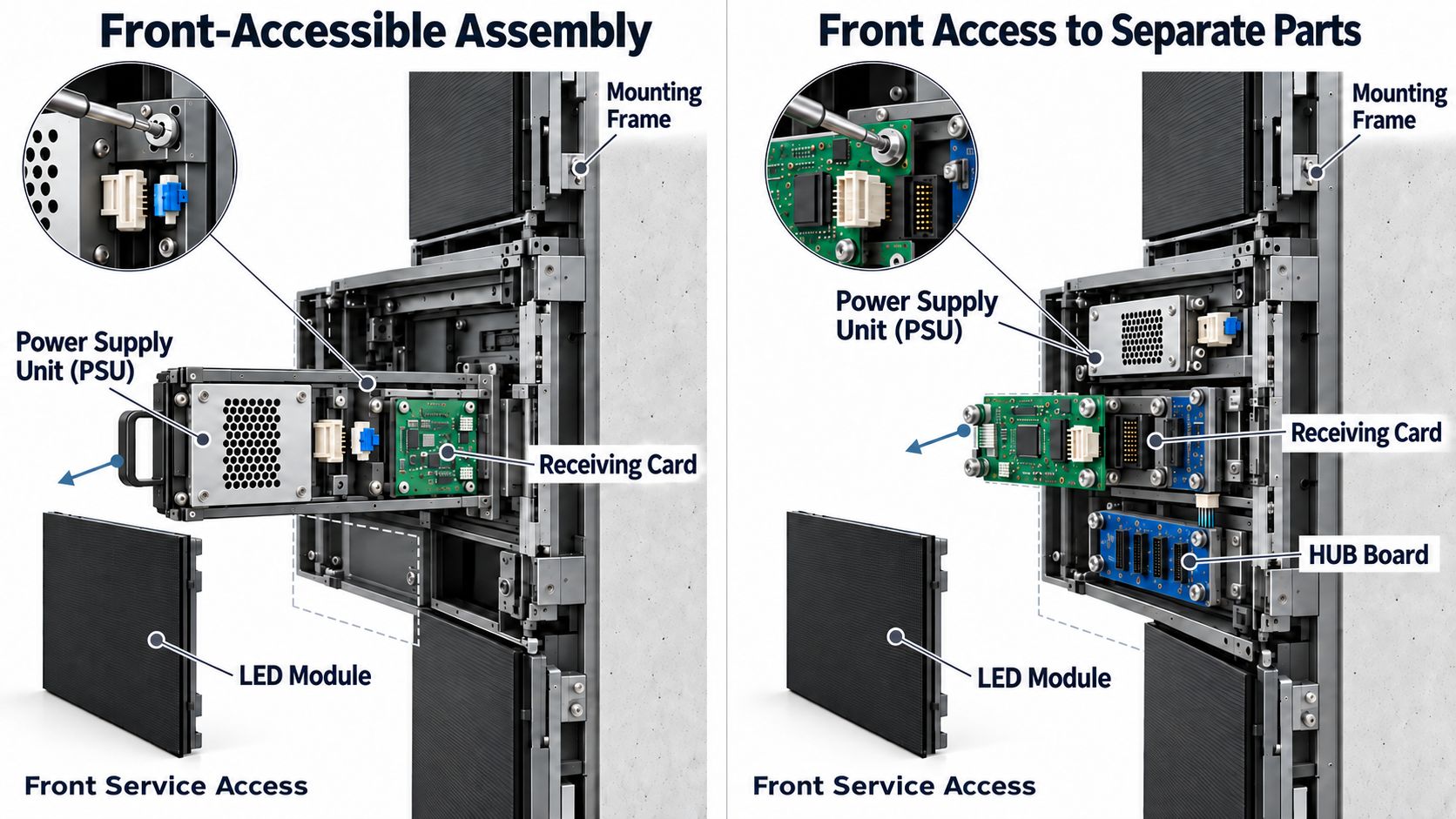
Exclude products whose critical parts cannot be reached after installation. Compare staff capabilities, deadlines, heat, and lifetime costs. “Front service” may cover only LED modules.
The following conditions determine which design to prioritize:
|
Project priority
|
Favor an integrated design when…
|
Favor a separate design when…
|
|
Restricted installation space
|
A combined assembly lifts out from the front but individual boards cannot be removed there
|
The PSU, receiving card, and HUB can all be removed from the front, while a combined assembly needs rear clearance
|
|
Strict recovery deadline
|
A configured assembly is on site and the entire replacement and setup meet the deadline
|
Staff can diagnose one part quickly, reach it easily, and still meet the same deadline
|
|
Local repair capability
|
Local staff can exchange a whole unit and send it to a repair center
|
Local staff can reliably diagnose and replace a PSU, receiving card, or HUB board
|
|
Spare inventory and cost
|
Fewer assembly types simplify on-site stock and the total cost of downtime, repair, and inventory is lower
|
Common individual parts serve multiple compatible cabinets and lower total inventory and repair cost
|
|
Heat and long operating hours
|
The assembly meets temperature limits at actual brightness, ambient temperature, and airflow, and fits the service window
|
The parts meet the same limits, and their placement offers a useful service advantage
|
|
Modular maintenance
|
The established workflow is whole-unit exchange followed by centralized repair
|
The project requires fault isolation and replacement of individual parts on site
|
|
Future upgrades
|
New assemblies have documented compatibility and a credible supply plan
|
New boards have confirmed compatibility with existing connectors, power, firmware, and other electronics
|
Neither design has an inherent thermal advantage. Measure temperature at planned brightness and ambient conditions with the final ventilation and mounting structure.
Ask where temperature is measured, how long the wall runs before readings stabilize, and whether the test reflects the intended duty cycle. Compare results with the specified operating limits.
Moving a PSU away from the wall can reduce local heat; this specific arrangement is not inherent to separate electronics.
Where displays must remain lit through a fault, specify power and signal redundancy. Quick replacement addresses recovery, not uninterrupted operation.
At remote sites, match spares to local skills and delivery times. For rentals, inspect connectors and rehearse recovery before events.
If both qualify, simulate identical PSU and receiving-card faults. Compare recovery, stock, labor, freight, repair, and downtime costs. Confirm supported cabinet revisions and spare numbers.
Removal does not guarantee upgradeability. New boards or assemblies must match the installed cabinet and firmware.
Frequently Asked Questions
Q1: If the PSU fails inside an integrated assembly, can our crew change only the PSU?
A1: That depends on the product's field service procedure. A removable PSU inside a box may still require a whole-box exchange on site. Compare the service manual with the spare part numbers before ordering stock.
Q2: Does “front service” include the power supply and receiving card?
A2: Not necessarily. Some products provide front access only for LED modules. Confirm the service direction for the modules, PSU, receiving card, and HUB separately, then request a demonstration on the proposed mounting structure.
Q3: Can a spare receiving card be installed straight from its box?
A3: Confirm the model, firmware, project configuration, and calibration recovery method first. At handover, install one of the supplied spares and inspect the resulting image. Do not assume settings restore automatically.
Q4: What should a rental company carry: complete assemblies or individual boards?
A4: Stock compatible assemblies if crews restore displays by whole-unit exchange. Stock individual parts if they can isolate faults reliably and remove the parts quickly. In either case, check spare configuration and connector condition before an event.
Q5: Will separate boards make future upgrades easier?
A5: Not necessarily. A new receiving card must match the existing interfaces, power, HUB board, and firmware. An integrated cabinet may also accept a compatible updated assembly. Confirm supported cabinet versions and replacement part numbers in writing.
Conclusion
Choose integrated electronics when the assembly is accessible, the service plan relies on whole-unit exchange, and compatible spares will be available where the wall operates.
Choose separate electronics when technicians can identify the failed part, remove it without excessive disruption, and make repair of individual parts and shared inventory economical.
Planning a COB LED wall?
Send Premteco's engineering team your installation drawings, service access details, cabinet count, operating hours, and required restoration time.
Ask the team to identify the four electronic functions and their board boundaries for the proposed cabinet. Then request a demonstration covering fault isolation, replacement, configuration recovery, and final image acceptance under your actual installation conditions.




